
")
")


Hotline Order:
+91 9727278672 / +91 8238235003
Email ID:
info@shipautomationparts.com
Free Shipping apply to all orders over $299
Safe & securely shopping
20 Day Returns in case u change your mind.
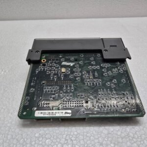
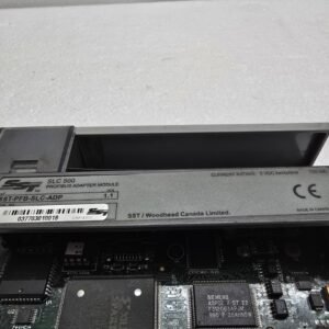
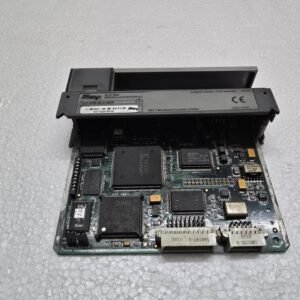
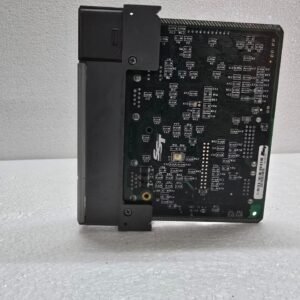
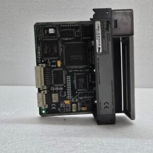
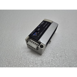
ALLEN-BRADLEY SST-PFB-SLC-ADP
₹21,309.00 Original price was: ₹21,309.00.₹15,287.00Current price is: ₹15,287.00.
The SST-PFB-SLC-ADP is a Profibus DP Slave Adapter module manufactured by SS1. Key Technical Specifications
The module acts as the “brain” of a remote rack, converting Profibus telegrams into SLC backplane signals.
| Feature | Details |
| Network Role | Profibus DP-V0 Slave |
| Compatibility | SLC 500 Fixed or Modular Racks (1746) |
| Max I/O Capacity | Up to 244 bytes of Input and 244 bytes of Output |
| Baud Rates | Supports up to 12 Mbps (Autodetect) |
| Address Range | 1 to 125 (set via rotary switches or software) |
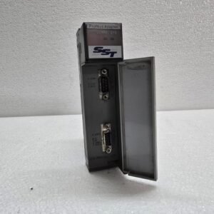
| Connection | 9-pin D-Sub (Standard Profibus) |
2. Physical Setup and Addressing
Because this is a slave module, it needs to be uniquely identified on the Profibus string.
-
Station Address: Usually set using the rotary switches located behind the front door. Ensure these are set before powering on the rack.
-
Profibus Connection: Use a standard Siemens-style 9-pin connector with a built-in terminating resistor.
-
Termination: If this module is at the physical end of the Profibus cable, the On/Off switch on the 9-pin connector must be set to “ON”.
3. I/O Configuration and GSD Files
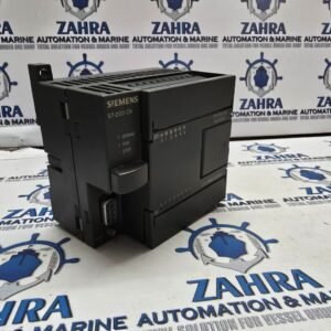
To make this module work with a Master PLC (like a Siemens S7-300 or S7-1500), you must have the GSD (General Station Description) file.
-
GSD File: The file is typically named
SST_0451.GSD. -
Configuration Tool: You import this GSD file into your Master’s configuration software (e.g., TIA Portal or Step 7).
-
Slot Mapping: You must manually define which 1746 modules are in which slots of the SLC rack within the Profibus Master’s hardware configuration. The order in the software must perfectly match the physical order in the SLC rack.
4. Status LEDs and Diagnostics
The module has several LEDs to help you diagnose the state of the network:
| LED | Status | Meaning |
| SYS | Solid Green | Module is powered and passed self-test. |
| COMM | Solid Green | Active data exchange with the Master. |
| COMM | Flashing Red | Configuration mismatch or no Master found. |
| SYS | Solid Red | Hardware failure. |
5. Common Troubleshooting Tips
-
Configuration Mismatch: The most common error is having a physical 1746-IB16 in a slot but configuring it as a 1746-IV16 in the GSD software. Even a small mismatch will prevent the COMM LED from turning solid green.
-
Backplane Power: The module draws its power from the SLC power supply (e.g., 1746-P1). If the rack power supply is overloaded by too many analog cards, the SST module may reset intermittently.
-
GSD Parameters: Ensure the “Input/Output size” defined in the Master matches the total number of words being used by the physical cards in the SLC rack.
Share:
 ALLEN-BRADLEY SST-PFB-SLC-ADP
₹21,309.00 Original price was: ₹21,309.00.₹15,287.00Current price is: ₹15,287.00.
The SST-PFB-SLC-ADP is a Profibus DP Slave Adapter module manufactured by SST (now part of Molex) specifically for the Allen-Bradley SLC 500 platform.
This module allows an SLC 500 rack to act as a “Remote I/O” station on a Profibus network. Instead of a standard CPU, this adapter sits in the first slot of the SLC chassis and communicates with a Profibus Master (such as a Siemens S7 PLC or an SST-PBMS-SLC scanner).
1. Key Technical Specifications
The module acts as the “brain” of a remote rack, converting Profibus telegrams into SLC backplane signals.
| Feature | Details |
| Network Role | Profibus DP-V0 Slave |
| Compatibility | SLC 500 Fixed or Modular Racks (1746) |
| Max I/O Capacity | Up to 244 bytes of Input and 244 bytes of Output |
| Baud Rates | Supports up to 12 Mbps (Autodetect) |
| Address Range | 1 to 125 (set via rotary switches or software) |
| Connection | 9-pin D-Sub (Standard Profibus) |
2. Physical Setup and Addressing
Because this is a slave module, it needs to be uniquely identified on the Profibus string.
-
Station Address: Usually set using the rotary switches located behind the front door. Ensure these are set before powering on the rack.
-
Profibus Connection: Use a standard Siemens-style 9-pin connector with a built-in terminating resistor.
-
Termination: If this module is at the physical end of the Profibus cable, the On/Off switch on the 9-pin connector must be set to “ON”.
3. I/O Configuration and GSD Files
To make this module work with a Master PLC (like a Siemens S7-300 or S7-1500), you must have the GSD (General Station Description) file.
-
GSD File: The file is typically named
SST_0451.GSD. -
Configuration Tool: You import this GSD file into your Master’s configuration software (e.g., TIA Portal or Step 7).
-
Slot Mapping: You must manually define which 1746 modules are in which slots of the SLC rack within the Profibus Master’s hardware configuration. The order in the software must perfectly match the physical order in the SLC rack.
4. Status LEDs and Diagnostics
The module has several LEDs to help you diagnose the state of the network:
| LED | Status | Meaning |
| SYS | Solid Green | Module is powered and passed self-test. |
| COMM | Solid Green | Active data exchange with the Master. |
| COMM | Flashing Red | Configuration mismatch or no Master found. |
| SYS | Solid Red | Hardware failure. |
5. Common Troubleshooting Tips
-
Configuration Mismatch: The most common error is having a physical 1746-IB16 in a slot but configuring it as a 1746-IV16 in the GSD software. Even a small mismatch will prevent the COMM LED from turning solid green.
-
Backplane Power: The module draws its power from the SLC power supply (e.g., 1746-P1). If the rack power supply is overloaded by too many analog cards, the SST module may reset intermittently.
-
GSD Parameters: Ensure the “Input/Output size” defined in the Master matches the total number of words being used by the physical cards in the SLC rack.

Reviews
There are no reviews yet.